Falling block action build along

Bailey Bradshaw

AH senior member
Joined
May 6, 2019
Messages
76
Reaction score
281
Location
Diana TX
Media
103
Building the first run of sidelever falling block actions, I've documented the process so far.

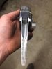
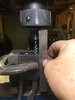
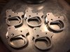
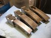
The first step obviously is to extract the action from the plate of 8620 steel in which it is contained. I am fortunate to have a wire EDM in house. While it is capable of far greater accuracy than is required for simply profiling the action, precision is never wasted.


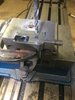
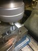
Once the batch of action bodies are all profiled, holes are drilled to located the starting point for the wire path to cut the breech block cavity, and a fixture is made to hole the actions during the cut.


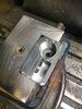
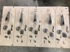
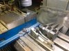
Breech blocks were wire cut before I started on the actions. The fit is extremely precise with .001" clearance for movement. Wire EDM is a very slow process and it's done under a powerful flush of water to cool the wire and clear eroded metal from the cut.


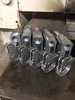
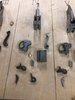
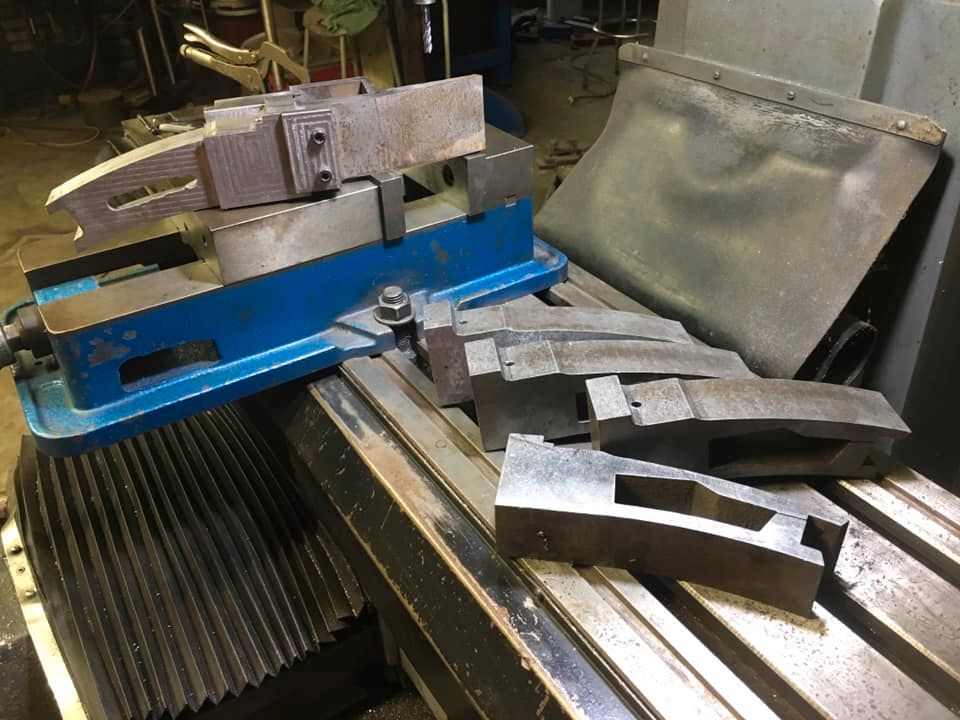
The tang surfaces are machined with tapers in both horizontal and vertical axis. There are also flats left on the interior edges of the tangs to index onto the inletting of the stock to negate any movement of the action once it's seated. Actions are secured to the stock with a drawbolt.

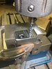
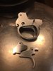
From there the pockets for the trigger group, cocking lever and extractor are machined. Also the hole in the side of the action for the sidelever stem.


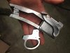
Actions are flipped over and the cartridge trough is machined in. A mock assembly of the sidelever, breech block and trigger group housing ( also made before the action bodies were started) is hard to resist.
 

Attachments

  • slfb1_zpssim2rnw0.jpg
    slfb1_zpssim2rnw0.jpg
    50.4 KB · Views: 274
  • slfb2_zpsespb5jba.jpg
    slfb2_zpsespb5jba.jpg
    78.6 KB · Views: 429
  • slfb3_zpsm4gdmpil.jpg
    slfb3_zpsm4gdmpil.jpg
    92.1 KB · Views: 313
  • slfb4_zpscqz7yn1w.jpg
    slfb4_zpscqz7yn1w.jpg
    40.9 KB · Views: 431
  • slfb5_zpsbixcaznb.jpg
    slfb5_zpsbixcaznb.jpg
    87.5 KB · Views: 187
Last edited by a moderator:


The trigger group is removeable and tuneable for pull weight and sear engagement. The rim of a cartridge can be used to push back the locking plunger at the rear of the trigger group pocket in the bottom tang.


Attachments

  • slfb11_zps1wt9b5pg.jpg
    slfb11_zps1wt9b5pg.jpg
    38.7 KB · Views: 563
  • slfb9_zpsf164y0hw.jpg
    slfb9_zpsf164y0hw.jpg
    47.3 KB · Views: 575
  • slfb10_zpsj5nuuckp.jpg
    slfb10_zpsj5nuuckp.jpg
    45.6 KB · Views: 275
  • slfb12_zps9ocvkduc.jpg
    slfb12_zps9ocvkduc.jpg
    76.4 KB · Views: 193
Last edited by a moderator:
Set in another fixture dedicated to the machining of the face of the action and associated steps. A 2" deep hole is drilled at the center of the hole for the barrel. This establishes the center of the bore and the center of the pocket for the striker and that the two are perfectly aligned.


The face of the action is trued to ensure it is perfectly perpendicular to the bore. This is where the barrel seats and is a very important step to ensure accuracy. Not unlike facing the end of a bolt rifle action.


Now the hole for the barrel can be machined. The breech block is in the action during this setup, so the bottom of the barrel hole will form the face for the breech block in a very precise manner. Not only will it be perpendicular, it is also machined to a known depth allowing the machining of the barrel shank to be done to the exact length. The breech block is tilted forward 3 degrees, so accurately cutting the breech block face any other way would be far more time consuming and wouldn't yield the precision this setup offers.

Also, the picture below shows the location of the center of the bore is well below the top edge of the breech block pocket. This allows the full diameter of the chamber, and case thrust for firing, are fully supported in the action. Even though the breech block extends to the bottom of the action, this helps prevent the case thrust from torquing the breech block and further localizing the area of the action that would absorb the case thrust. Having the camber area fully supported keeps the distribution of the case thrust over a much more broad area.


Attachments

  • slfb16_zpsdpfmaqxx.jpg
    slfb16_zpsdpfmaqxx.jpg
    68.8 KB · Views: 187
  • slfb15_zpsbzl3ru8r.jpg
    slfb15_zpsbzl3ru8r.jpg
    76.7 KB · Views: 204
  • slfb14_zpstbojr4q9.jpg
    slfb14_zpstbojr4q9.jpg
    30.8 KB · Views: 170
Last edited by a moderator:
With the barrel hole machined, the threads can be machined with a thread mill. Precision threads cut in perfect alignment with the hole, the action face and breech block face.


The finished barrel shank hole and threads


Attachments

  • slfb17_zpsomv0qkv4.jpg
    slfb17_zpsomv0qkv4.jpg
    63.9 KB · Views: 166
  • slfb18_zpskhioklbu.jpg
    slfb18_zpskhioklbu.jpg
    86.1 KB · Views: 283
Last edited by a moderator:
trigger group housings. First profiled out of 1/2" plate, holes spotted for the pivot points of the trigger and sear, and a window that displays the trigger/ sear engagement.


The housings are then surface ground to final thickness, slotted to accept internal parts, holes drilled and reamed, and the parts are deburred.

.
 

Attachments

  • slfb20_zpsav1md9jm.jpg
    slfb20_zpsav1md9jm.jpg
    58.4 KB · Views: 180
  • slfb19_zpstmg3k4bu.jpg
    slfb19_zpstmg3k4bu.jpg
    89.9 KB · Views: 173
Thank you for taking the time to post your progress. This is fascinating to watch.
 
The thread mill is an entirely new concept to me. Would it be possible to show a slow motion video of how it works? My thread cutting experience is limited to the use of taper and bottom taps.
 
Very interesting. I love falling block actions and it's great to see how they're made
 
The thread mill is an entirely new concept to me. Would it be possible to show a slow motion video of how it works? My thread cutting experience is limited to the use of taper and bottom taps.
I will shoot a video of the thread mill next round, honestly is a bit like watching paint dry. Slow feed rate. Essentially, the thread mill follows a spiral toolpath that is generated in CAD. I use a single thread cutter. There are other thread mills that can cut multiple threads in one pass, but they are dedicated to one thread pitch. A single cutter can cut a wide variety of thread pitches and diameters. All thread mills follow a spiral tool path though.
 
Triggered.....

Triggers and sears installed in the housings. Next will be to install springs, adjustment and set screws. The triggers are adjustable for pull and seat engagement. The larger house in the housing is for viewing the sear/trigger engagement.

Also, the pivot point for the trigger is towards the rear. This reduces the amount of travel at the blade of the trigger, but amplifies the travel at the front. This reduces felt creep. The forces acting on the trigger from the mainspring to the sear are perpendicular to the pivot point of the trigger. Again, to reduce drag, creep and helps make the trigger more crisp


Attachments

  • slfb22_zps5o5ai8kr.jpg
    slfb22_zps5o5ai8kr.jpg
    81.6 KB · Views: 159
  • slfb21_zpsca1gxsfa.jpg
    slfb21_zpsca1gxsfa.jpg
    58.9 KB · Views: 496
Last edited by a moderator:
Organization always helps productivity especially when working on several at a time. Just a few components left to make and assembling then begins


Attachments

  • slfb23_zpsr2rjybwu.jpg
    slfb23_zpsr2rjybwu.jpg
    64.7 KB · Views: 175
  • slfb24_zpsooa5yioz.jpg
    slfb24_zpsooa5yioz.jpg
    57.1 KB · Views: 171
Last edited by a moderator:

Forum statistics

Threads
54,067
Messages
1,144,851
Members
93,546
Latest member
Lepani


Latest posts

Latest profile posts

Black wildebeest hunted this week!
Cwoody wrote on Woodcarver's profile.
Shot me email if Beretta 28 ga DU is available
Thank you
Pancho wrote on Safari Dave's profile.
Enjoyed reading your post again. Believe this is the 3rd time. I am scheduled to hunt w/ Legadema in Sep. Really looking forward to it.
check out our Buff hunt deal!
 
Top